Please contact us at [email protected]
Call us at 817-684-1216
Air Conditioning Copper Theft Solutions
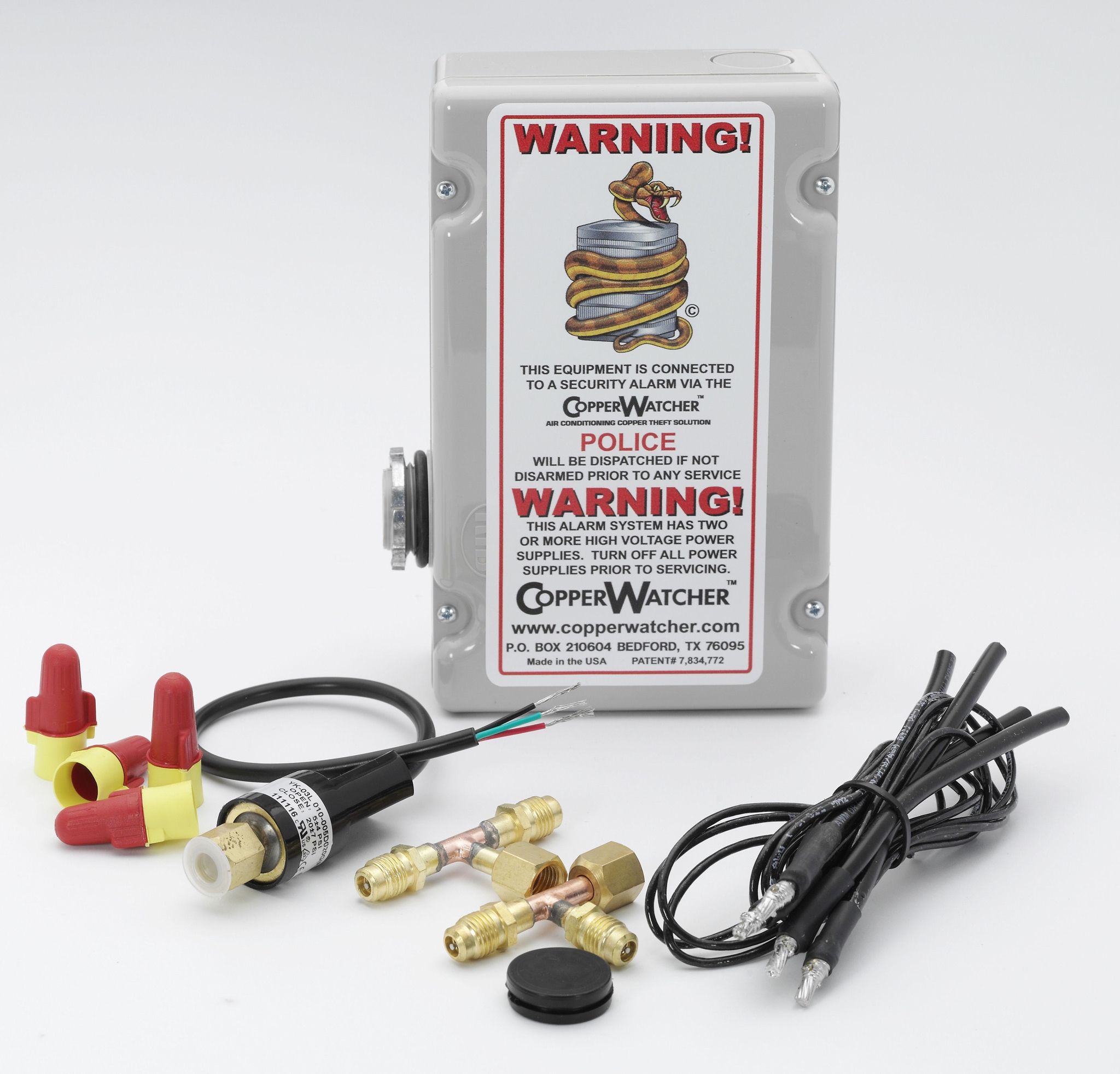
The CopperWatcher™ is the premier solution to the explosion in air conditioning coil theft for scrap copper. CopperWatcher™ targets the connections thieves’ compromise to steal an air conditioner with unsurpassed reliability. CopperWatcher stops thieves as early in the theft attempt as possible.
CopperWatcher™ Copper Theft Solution Learn About CopperWatcher™
CopperWatcher™ supervises power and refrigerant pressure to the A/C. When power is shut off, or copper tubes are cut, the CopperWatcher™ sends a signal to the existing burglar alarm system. The burglar alarm systems loud siren sounds drawing attention to the would-be thieves. CopperWatcher™ is intelligent enough to tell the difference between a purposeful shut down and a local power outage, and will not send a “false alarm” to the security panel. Saving you a possible fine with your local authorities and the nuisance the audible alarm will cause.
Purchasing CopperWatcher
CopperWatcher is available on line at the CopperWatcher store. Licensed Alarm and Air Conditioning contractors click this link Online Registration and register for wholesale pricing. Alarm and HVAC distributors call in for distributor pricing 817-684-1216.
Bob Frederick
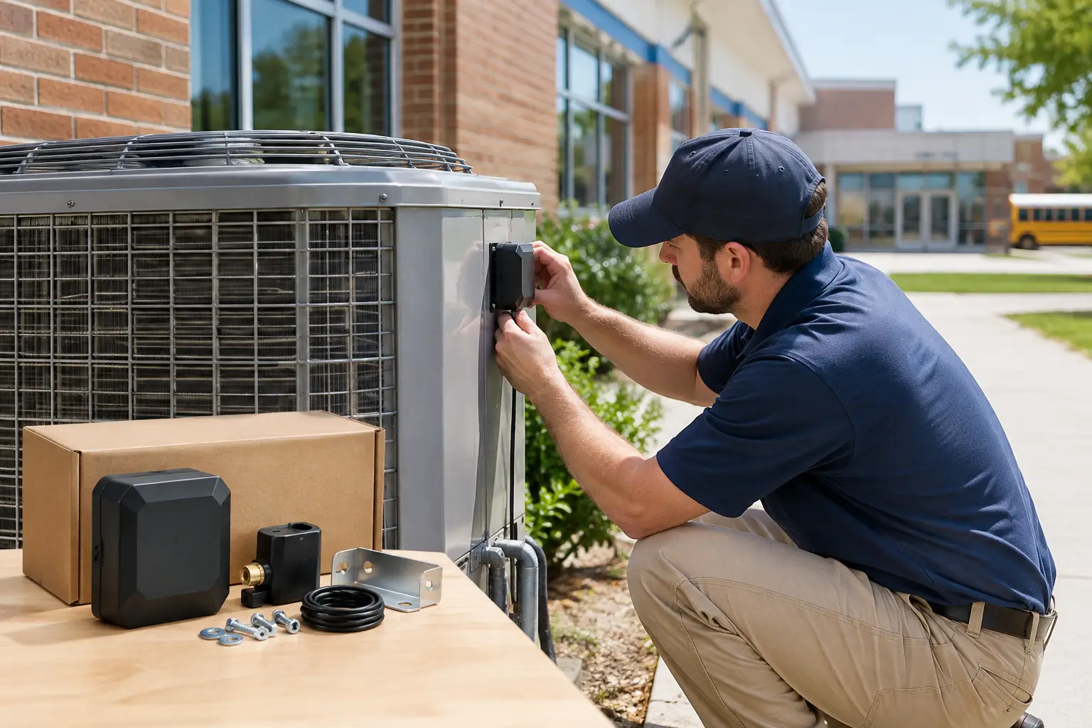
A disabled condenser behind a classroom can become a much larger problem than a repair ticket. When copper refrigerant lines or coils are damaged or removed, schools can face equipment loss, disrupted learning, uncomfortable classrooms, emergency HVAC service, and difficult budget decisions. To protect school air conditioners effectively, facilities teams need a plan that treats exposed outdoor units as both mechanical assets and security assets.
The strongest approach is layered. Physical barriers can slow access, good lighting can increase visibility, and alarm-based detection can call attention to an attempt while it is still underway. No single measure fits every campus, but combining the right controls for each location gives school districts a practical way to reduce exposure without rebuilding their entire security program.
Why School Air Conditioners Need Special Protection
Schools often have conditions that make outdoor HVAC equipment difficult to watch continuously. Condensers may be located behind buildings, near athletic areas, on service sides of portable classrooms, or in fenced mechanical yards that are quiet after hours. Larger campuses can also have dozens or hundreds of units spread across multiple buildings.
That distribution matters. A thief does not need access to an entire campus to cause substantial loss. One damaged unit can affect a classroom wing, administrative office, kitchen, server room, or other space that cannot simply wait for a routine service visit. If the equipment is older or replacement parts are delayed, downtime can extend beyond the initial incident.
The risk is not limited to equipment replacement. Cutting refrigerant lines can release refrigerant and leave a system requiring qualified HVAC evaluation, repair, evacuation, and recharge. Facilities leaders should account for the total operational impact, not just the value of the missing copper.
Start With a Campus Exposure Review
Before selecting security equipment, walk the property after school hours or review it from the perspective of someone looking for an unnoticed path to a condenser. The goal is to identify units that are accessible, concealed, lightly monitored, or essential to building operations.
Pay attention to condensers near alleys, wooded edges, rear parking areas, loading areas, detached buildings, portable classrooms, and rooftop access points. Also identify units behind solid fencing or landscaping that may hide activity from staff and neighbors. A fenced enclosure can protect equipment from casual contact, but if it blocks all sightlines and has no monitored entry or alarm coverage, it may also provide privacy for an intruder.
Prioritize equipment by consequence as well as visibility. A small unit in an exposed location may deserve attention, but a condenser serving a nurse’s office, technology room, food-service area, or heavily occupied classroom zone may create greater disruption if it is taken offline. This review helps a district direct its budget toward the units where prevention will have the highest value.
Consider the School Calendar
Risk conditions change throughout the year. Long weekends, holiday breaks, summer recess, and construction periods can leave campuses quieter than usual. A unit that is highly visible during the school day may be largely unobserved during a break.
Facilities teams should also consider when air conditioners are intentionally shut down. A security plan must accommodate normal seasonal operation, planned maintenance, and occupied versus unoccupied schedules. Detection that cannot distinguish ordinary operational changes from suspicious conditions can create unnecessary dispatches and nuisance alarms.
Use Physical Security to Delay Access
Physical protection has a clear role: it creates time and effort between an intruder and the equipment. Lockable cages, properly designed protective enclosures, secured gates, tamper-resistant hardware, and protected line-set pathways can make a condenser harder to reach and less convenient to damage.
The details matter. An enclosure must allow safe HVAC service access, airflow, drainage, and required electrical clearances. It should not obstruct service panels, trap heat around the unit, or force technicians into unsafe work positions. Work with a qualified HVAC professional when selecting or modifying barriers so equipment performance and maintenance access are not compromised.
Lighting and landscaping deserve the same practical attention. Trim vegetation that conceals units or access routes. Repair exterior lighting near mechanical equipment, walkways, and gates. If lighting is controlled by timers or photocells, test it during the hours when the building is unoccupied rather than assuming it operates as intended.
Physical measures are valuable, but they are not a complete answer. A determined person may still cut through a barrier or work around it. That is why delayed access should be paired with a means of detecting the actions associated with an attempted theft.
Protect School Air Conditioners With Early Detection
The most useful alarm response occurs before a thief has time to remove valuable components and leave the site. For air-conditioning equipment, two actions are especially significant: interrupting electrical power to the unit and cutting the copper refrigerant lines.
A dedicated A/C theft-detection device can monitor those conditions and communicate with the property’s existing burglar-alarm system. When suspicious power and refrigerant-pressure conditions are detected, the burglar-alarm system can activate its siren and follow the property’s established monitoring or notification plan. This gives the event immediate attention instead of relying on someone to discover damage during the next building walk-through.
CopperWatcher™ CW-3 is designed around this early-stage approach. It monitors electrical power and refrigerant pressure at the A/C unit, addressing the primary actions commonly associated with condenser and copper theft attempts. Its intelligent monitoring is intended to distinguish an intentional A/C shutdown from a local power outage, helping reduce false alarms and the potential costs that can accompany them.
For schools, integration is often more practical than creating a separate security system. A district may already have an alarm panel, siren, monitoring procedures, and staff call tree in place. Adding compatible A/C theft protection allows the existing alarm infrastructure to play a more targeted role at exposed condensers. It does not replace the burglar-alarm system, routine HVAC service, or law-enforcement response, but it can strengthen the overall protection plan.
Coordinate Security and HVAC Teams
A/C protection performs best when the alarm contractor and HVAC contractor communicate before installation. The security professional needs to understand the alarm-panel connection, zone configuration, notification procedures, and any local false-alarm requirements. The HVAC professional needs to confirm where power and refrigerant connections can be safely monitored and how the system will be serviced after installation.
This coordination also makes later troubleshooting easier. Document which protected device corresponds to each condenser, the building served, relevant alarm zones, shutoff locations, and the process for authorized service. When staff changes occur, that record can prevent a routine repair from becoming an avoidable alarm event.
Build Procedures Around the Equipment
Technology works best when people know what to do with the information it provides. School districts should establish a clear after-hours response process for A/C-related alarm activity. Depending on the property and monitoring arrangement, that may include an alarm-monitoring company, designated facilities staff, security personnel, and local law enforcement when appropriate.
The response plan should state who verifies the alarm, who contacts HVAC service if damage is found, and who documents the event for insurance or maintenance records. It should also define how authorized contractors place equipment on test or coordinate planned shutdowns. Clear procedures protect staff, reduce confusion, and help avoid repeat problems.
Routine inspection remains necessary. During scheduled HVAC maintenance, inspect cages, locks, fences, conduit, refrigerant lines, and alarm-related components for damage or signs of tampering. Test security and alarm functions according to the manufacturer’s guidance and the district’s alarm-service schedule. A system that is installed but never checked may create a false sense of protection.
Match the Investment to the Site
Not every condenser needs the same level of protection. A newer unit behind a locked, well-observed service area may need a different strategy than an exposed unit behind a portable classroom or a critical system serving a specialized space. The right decision depends on access, visibility, equipment value, operational importance, prior incidents, and the campus’s current alarm capabilities.
For a single-building school, a targeted upgrade at the most exposed units may be the sensible first move. For a district with multiple campuses, standardizing the assessment process, installation approach, labeling, and alarm response can make protection easier to manage over time. Licensed alarm contractors, security integrators, and HVAC professionals can help translate a site assessment into an installation plan that respects both security and mechanical requirements.
Protecting outdoor HVAC equipment is ultimately about preserving the conditions students and staff depend on. A well-planned combination of access control, visibility, early detection, and disciplined response gives schools more time to act before a theft attempt becomes lost cooling, emergency repairs, and an avoidable interruption to learning.